But now the facade has been be fabricated, transported and mounted, and it is time to judge the final results.
Let us start with the construction phase. I am not found of surprises and that is why I detailed the facade down to the nuts and bolts. I was concerned that the manufacturer was not able to deliver good solution for important detail/concepts and therefor I wanted to be proactive. The result was that there were no bad surprises making the modules or when mounting them to the building.
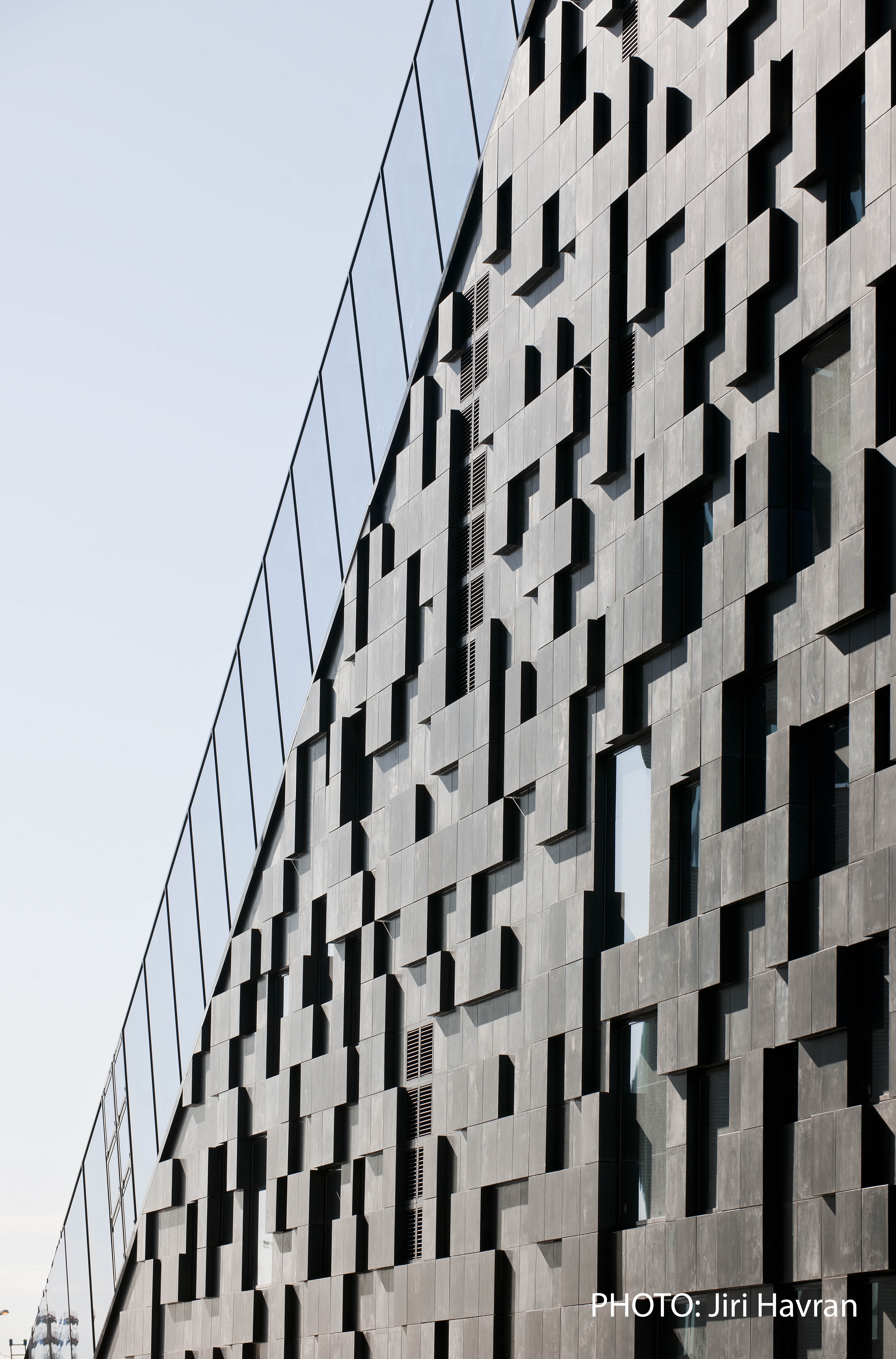
And frankly, I am quite happy with the facade. I like how the facade reflects the light on the aluminium cladding, and the champagne color is playing well with the surrounding buildings. And keep in mind it is not an expensive facade, but together with the manufacturer we have found good solutions that we have discussed thoroughly.
I have been taking a lot of photos lately to test different photogrammetry software, and sometimes I feel that the results is better than it should have been since I usually shoot from my hip.
One of my favorite programs is Memento from Autodesk that is a really great software. Memento is in Beta mode but has the tools you need to generate a mesh/pointcloud from your pictures. The interface is really great and it is easy to use.
It has some issues with Z-direction and scaling when you export it, but hopefully they will fix this bug shortly. It is also frustrating that it is not possible to import the mesh into Revit. Therefor you need to export the model as a pointcloud to import it to Revit, and that is a pity. It would have been great to use the mesh to create sun study for instance, or to create the surroundings to your project. This is not a Memento problem. It is a Revit problem.
Remember to import your cool models into Sketchfab so you can show them to your colleges or embed them into your homepage (if they support it…) 🙂
Sometimes new technology needs to mature before it is efficient or useful to use in the daily work. And as an architect, I always need to balance the time and effort to play with new tools that may be useful in the future.
Photogrammetry on the other hand is not a new technology anymore. But since new software makes the process much smoother, and the prices for drones has been dropping, there is a lot of new potential with this technology.
That is why I have made a couple of case studies lately, to understand the limitation and possibilities for a real life project. My first experiment is with the DJI Phantom 2 drone, and I wanted to see what kind of accuracy I got from the mesh and the pointcloud from the photogrammetry.
I was rather impressed to see the results if you take in consideration that the drone only took 31 photos, but maybe it is not accurate enough to use it in the design phase. But then again, how accurate do you actually need the surroundings to be? When you import it to Revit, the pointcloud may give value as an reference.
Special thanks to Geomatikk Survey for the excellent drone service.
Just imagine the power of combining a lasercutter and gingerbread. I have talked about it many times, and it was time to «walk the talk».
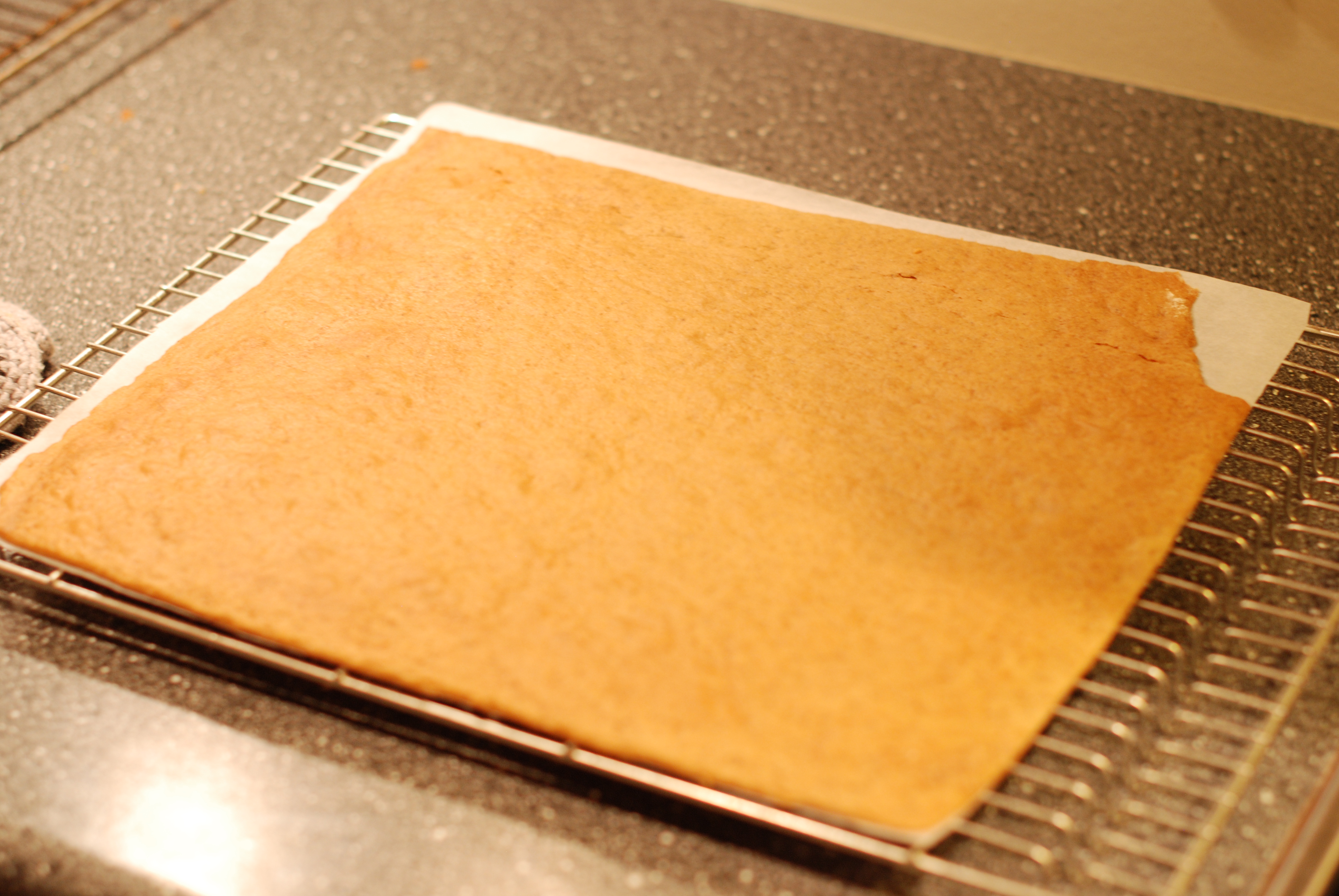
Step 1: Roll’it out
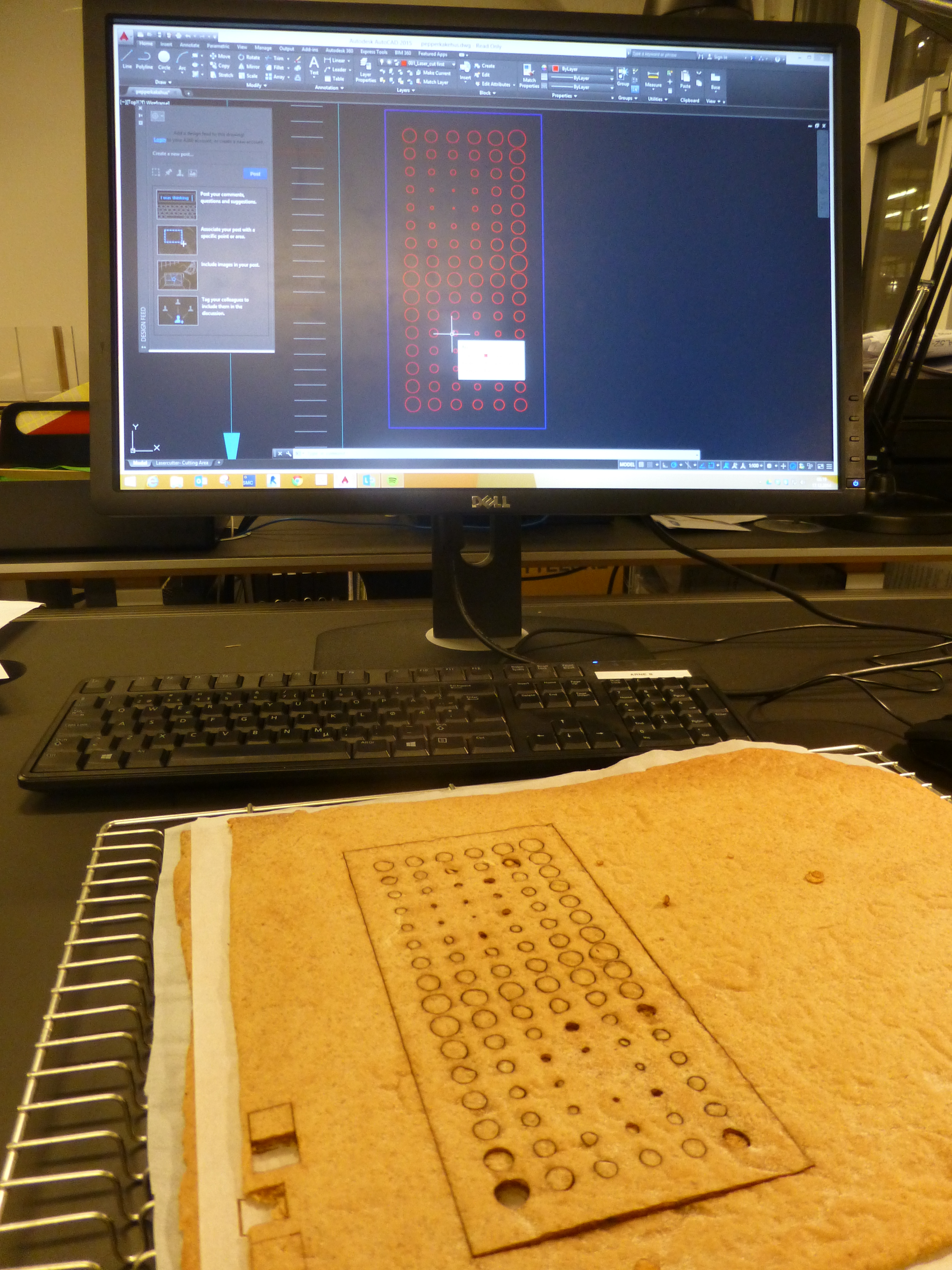
Step 2: Lazzzer it up
Step 3: Reviewing the results
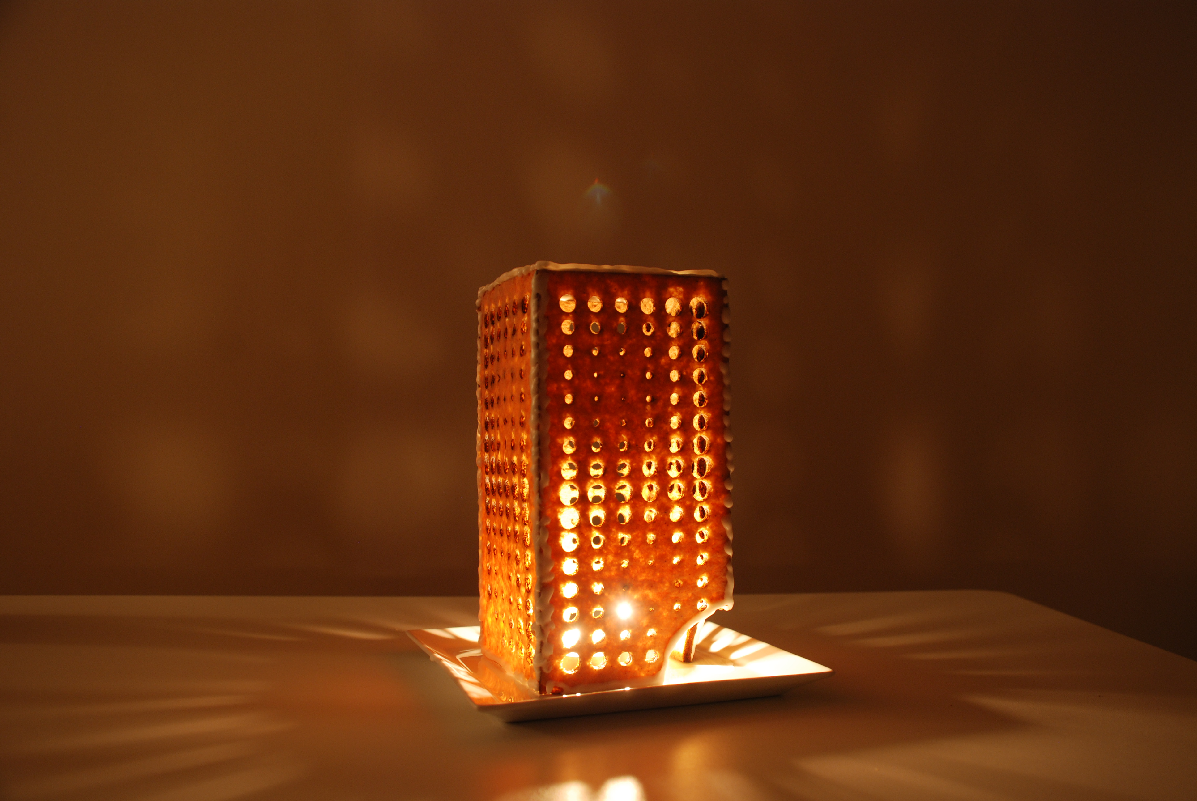
Step 4: Assembly
Conclusion
Despite the smell of burned gingerbread, the results of my first lasercutted gingerbread is promising. Next year I will take it to the next level so stay tuned. Merry Christmas!!
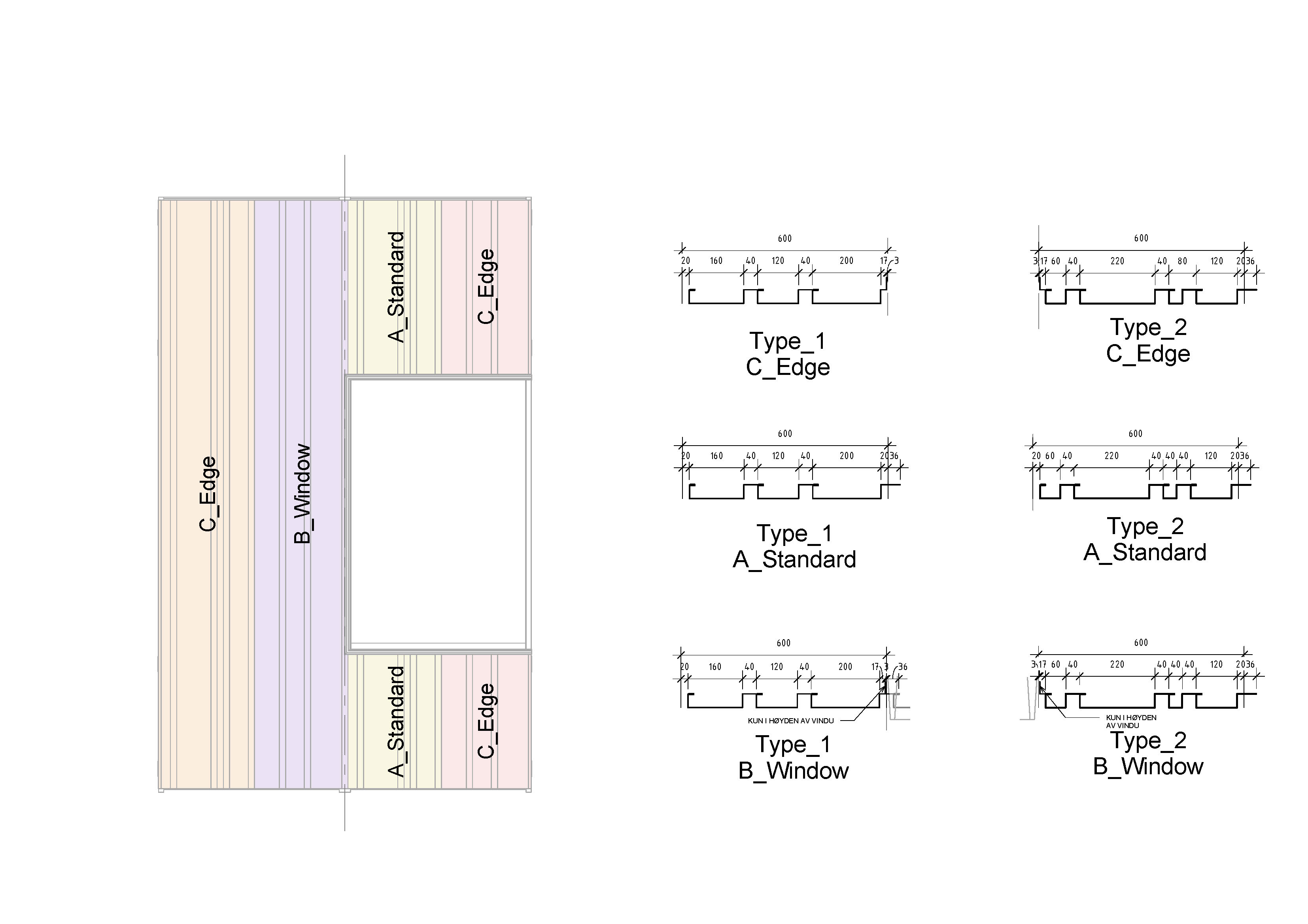
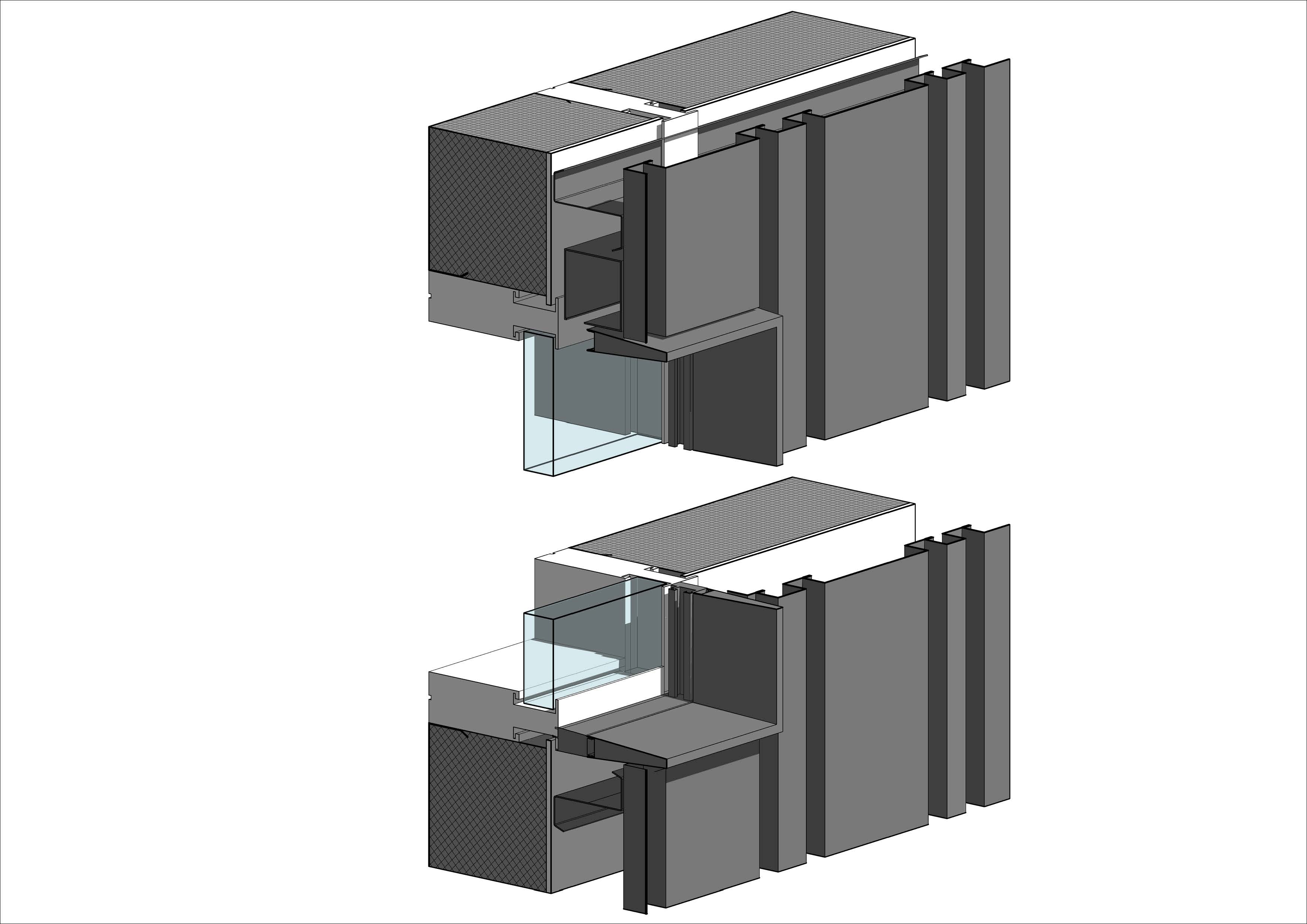
It is made of aluminum plates with two different sets of profiles (see picture above). These two different profiled plates are mounted one after the other, and since the module is 2400 mm and the width of every plate is 600 mm, there will be two plates of each type on every module.
Within every module, the aluminum plates are either on the border of the module, towards a window or towards another plate. These three different positions have an impact on how the edges of the two different plates will be (see picture above).
I have made these two profiled plates as two different curtain wall panel families in Revit for various reason. One of the reason is that sometimes the width is less than 600 mm, and then I want to keep either the left or the right side of the curtain wall panel in a fixed position.This will avoid the position of the profiled plates from shifting from each other (this is illustrated in the video).
The two curtain wall panels is basically made in the same way that I demonstrated in «Family training#1 -CWpanel with array» but in a slightly more complex way. The reason that I can’t do it in the same way, is that I need this family to be 100 % accurate due to production. I can’t simply divide the width of the curtain wall panel with the width of the profiles since this will be to inaccurate. Therefore I have added a little new flavor into the family, and that is a couple of «IF» statements and a profile that can varies between the profile closest to the curtain wall grid (see picture above).
In this way I can simply make a schedule that counts every family and types, combined with height and width parameter, and voilà. You are close to production.
We are working on a project where the facade will be a prefabricated modular facade, where the modules will arrive at the construction yard ready to be mounted on to the slabs. Since the modules contains everything from exterior cladding, exterior shading, insulation, interior wall cladding, there will be no need to do anything more with the facade after every module have been mounted.
The reduced construction time at the construction yard is one of the reason it is getting more and more popular with prefabricated modular facades. It is also getting increasingly popular because of reduced cost and increased precision.
There are many ways of modeling a modular facade in Revit, and it varies from project to project. In this project I have used a lot of Curtain Walls and Groups, which has some pros and cons. I will divide this Case Studie in multiple parts, where this part will cover the general principles of model with groups.
The width of each module is 2400 mm and the height is in 3800 mm. This will give the facade a modular grid. You should try to have as few types of modules as possible since the amount of different modules usually will have a cost effect. Sometimes you have to balance the amount of different types of modules with the amount of flexibility. But not always. This is specially important in the early stages of the project, because if you can’t keep it simple in the start you may end up with a to «complex» end result.
Every module type is one group. so if you have 10 different types of modules you will have 10 different types of groups. Some tips using groups:
Keep the amount of groups down to a minimum. The illustration above shows you that in the finale phase of your project, you will have many different groups. . The more groups you have, the more you have to maintain. BUT, you should never stop doing what you want to do with your project because you don’t want to make more groups…
Group origin. One of great thing of using groups, is that you can change one group with another to test different concepts. To be able to do this, every group has to have the same group origin
Disallow join. The groups are going to be stacked together, and you don’t want your walls within a group to magically join with the neighbor group. Therefor,disallow join as much as possible
In this facade I almost only uses Curtain Walls with different Curtain Wall Panels and Mullions. I will explain this in depth in my next blog post.
Remember, all the hard work you are using modeling your facade in 3D, you will be able to harvest directly from your model to production drawings. And that is a great feeling!
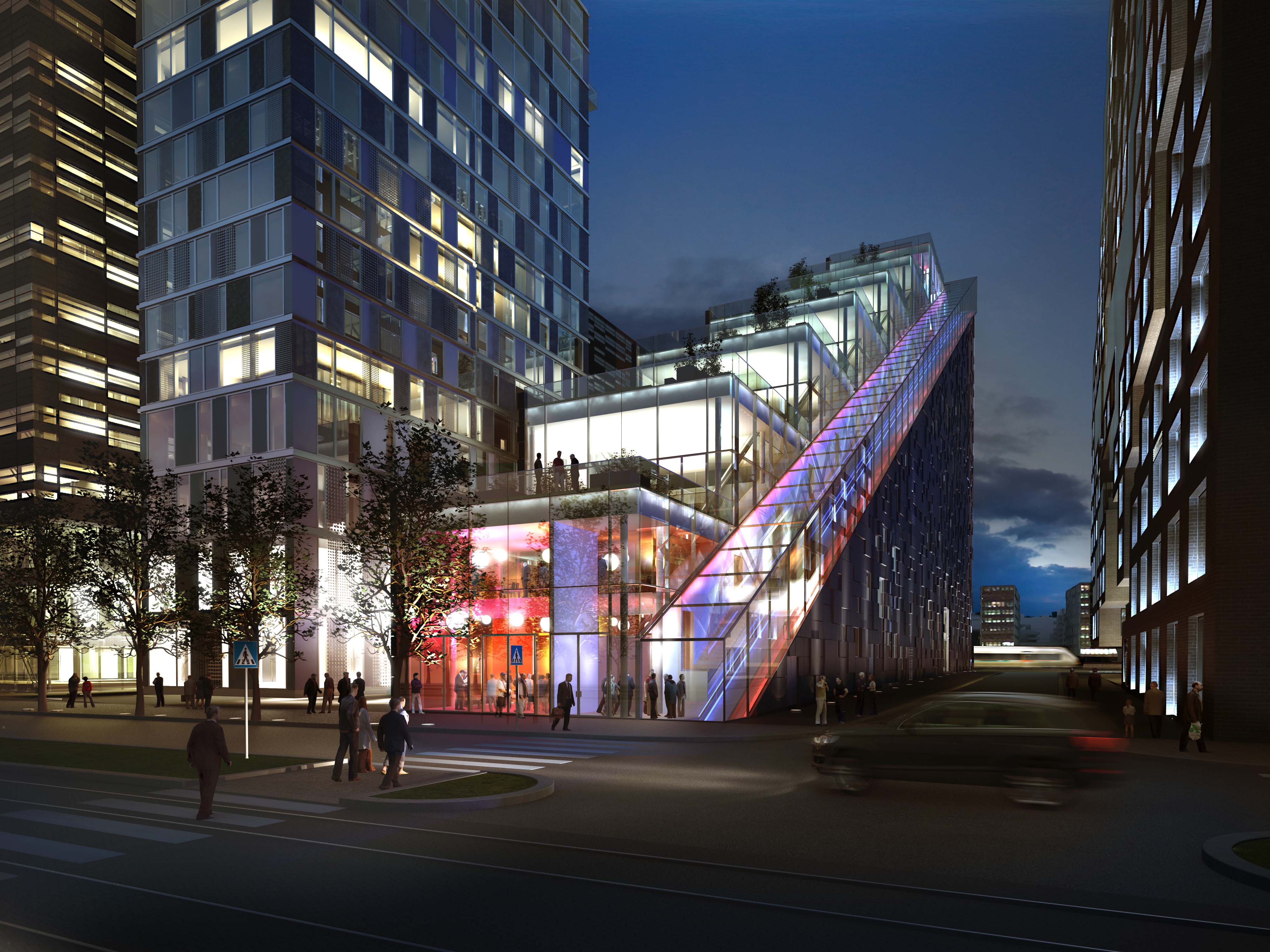
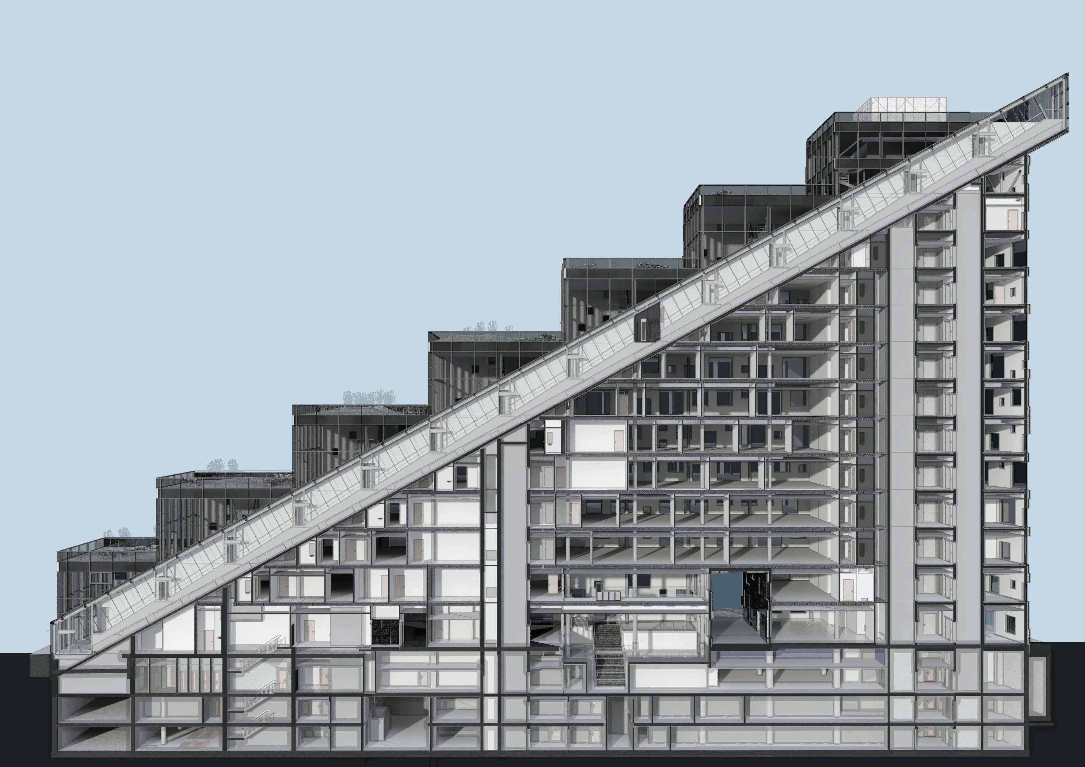
DNB’s new headquarter consist of three buildings with a underground story that connects the buildings together. The building to the far west is designed by Dark Architects, and since the shape of the building i like a stair, it is not a strait forward answer how to make the internal flow efficient with minimum amount of cores. There is also a public roof and a restaurant on the top of the building, so in addition to find the best solution for the many employees in the building, we also had to work out how we could bring the many guests to the spectacular view from the public roof.
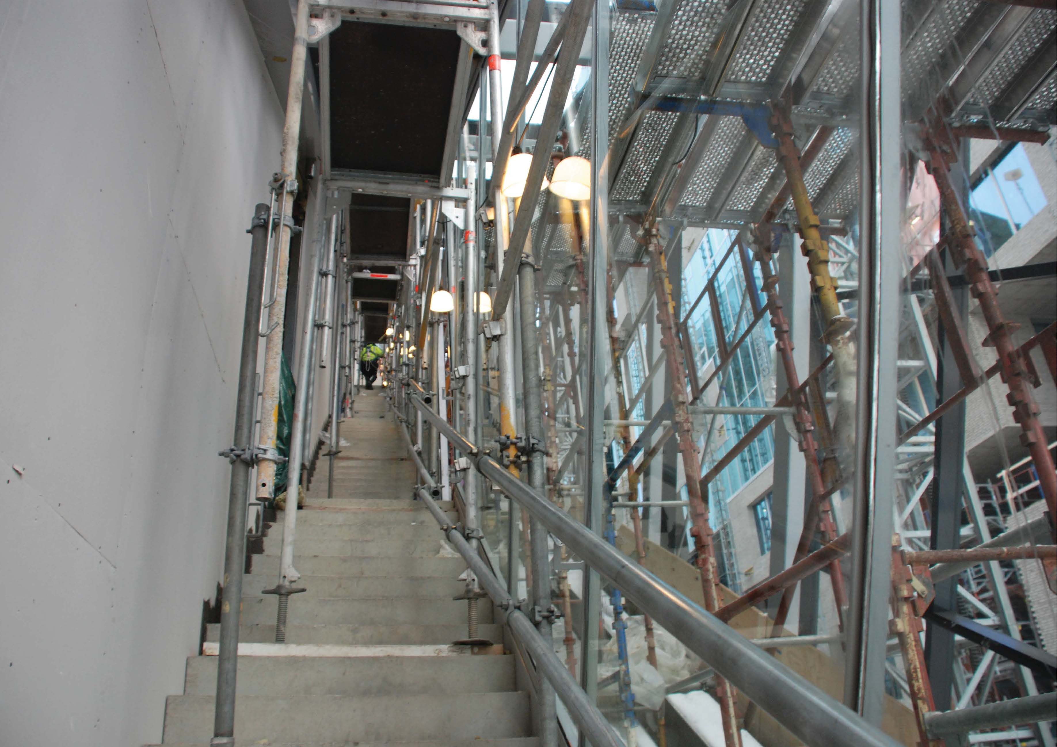
The solution was an inclined public elevator that is more than 110 meters long that only stops at ground floor and the top floor, and along the elevator shaft there is a strait stair that connects all the floors in the building. This stair has many names such as «Stairways to heaven» and recently there has been a competition who can be the fastest up all the 303 treads (http://www.dn.no/dnaktiv/2014/05/09/Lping/303-trappetrinn-p-54-sekunder).
The design process was a joyful ride. When a horizontal slab meets an inclined slab, there will always be some interesting discussion. In addition will the angel of the inclined elevator have direct impact on how the stair will be, since everything is dependent on each other. To feed the project with valuable drawings, I had great success to combine regular floor plans / sections together with isometrics 3D views.
In this project we started using ebeam, and we found it very useful in many meetings and discussions. Suddenly everybody could draw something that everybody could see and participate in.
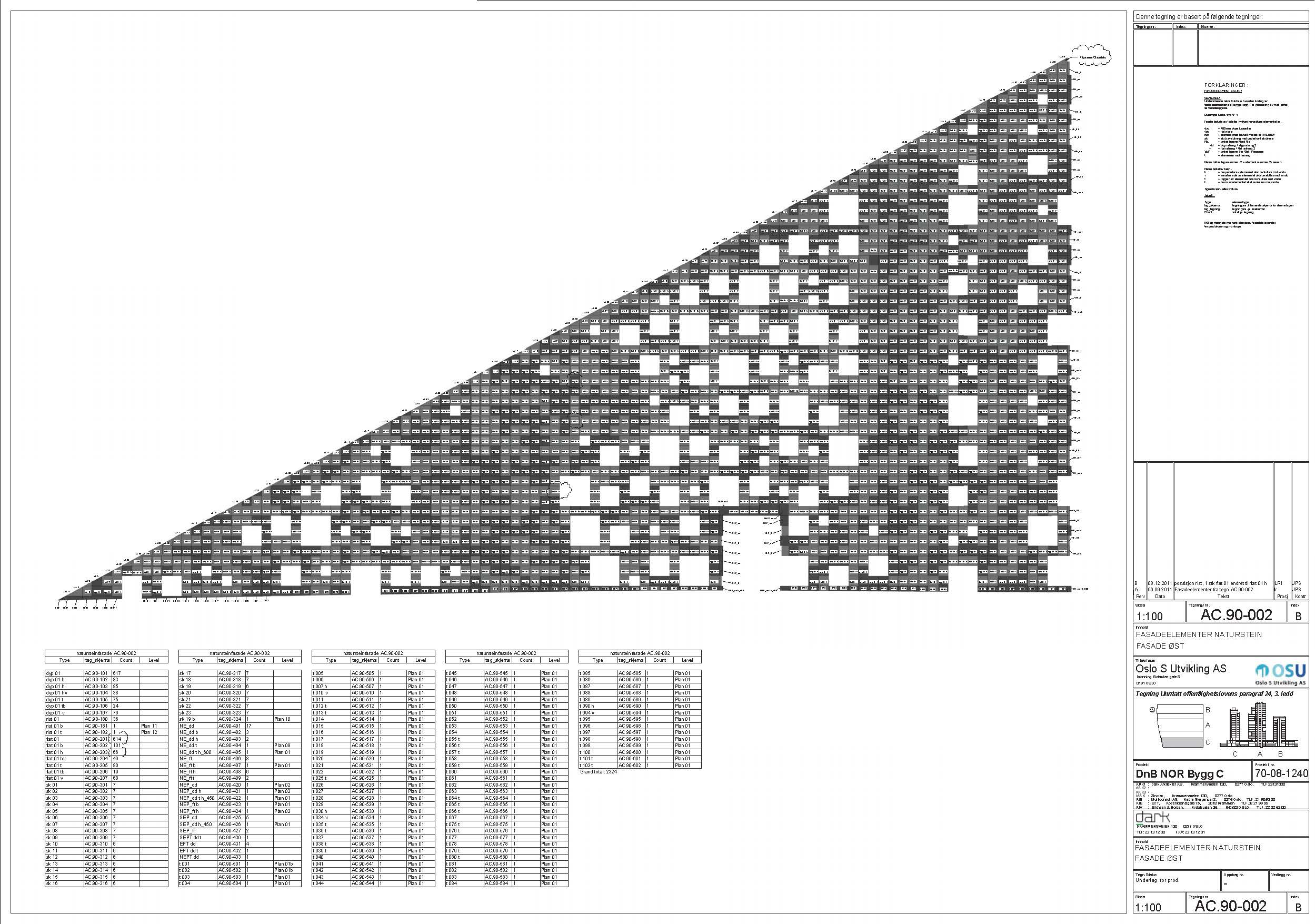
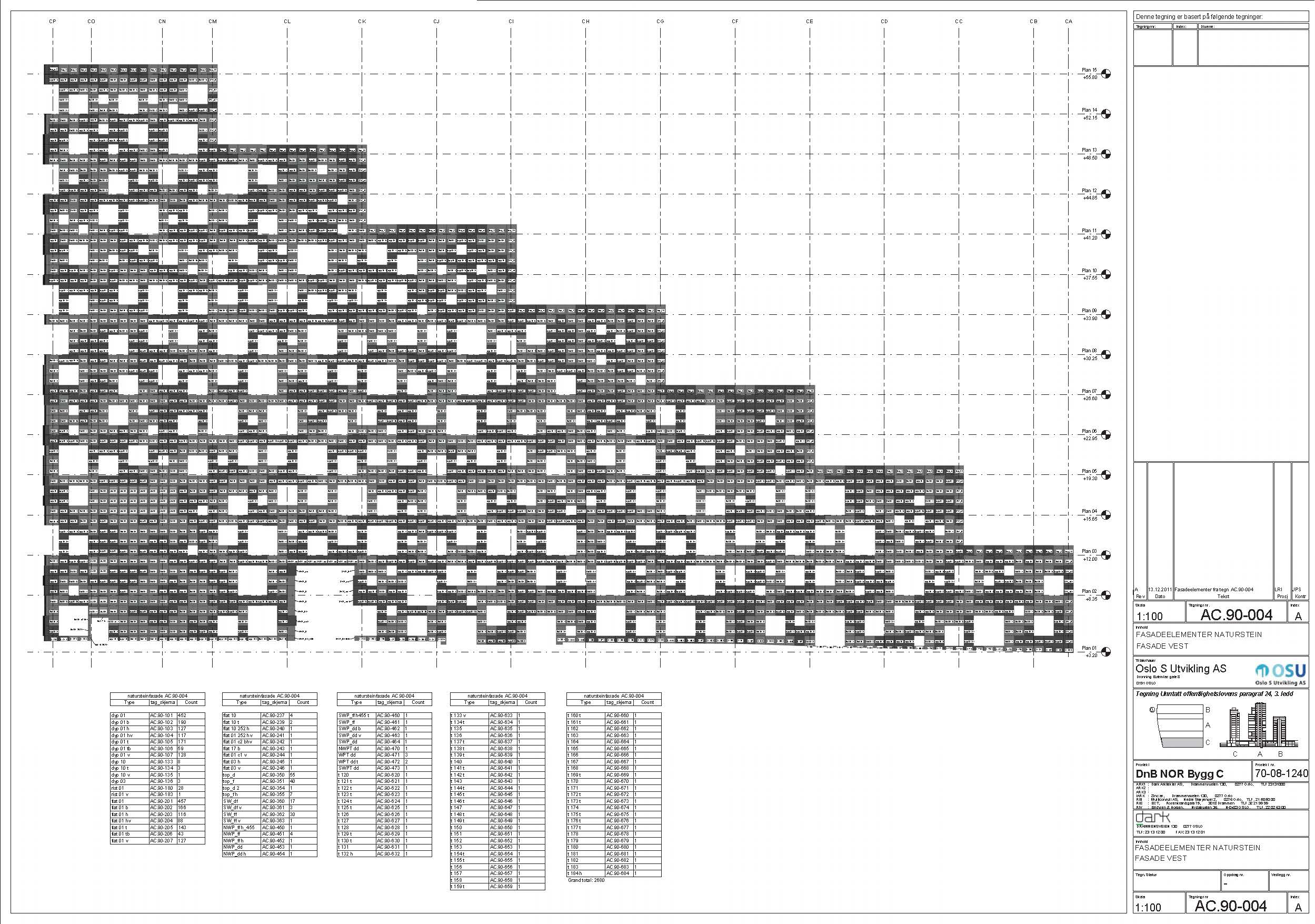
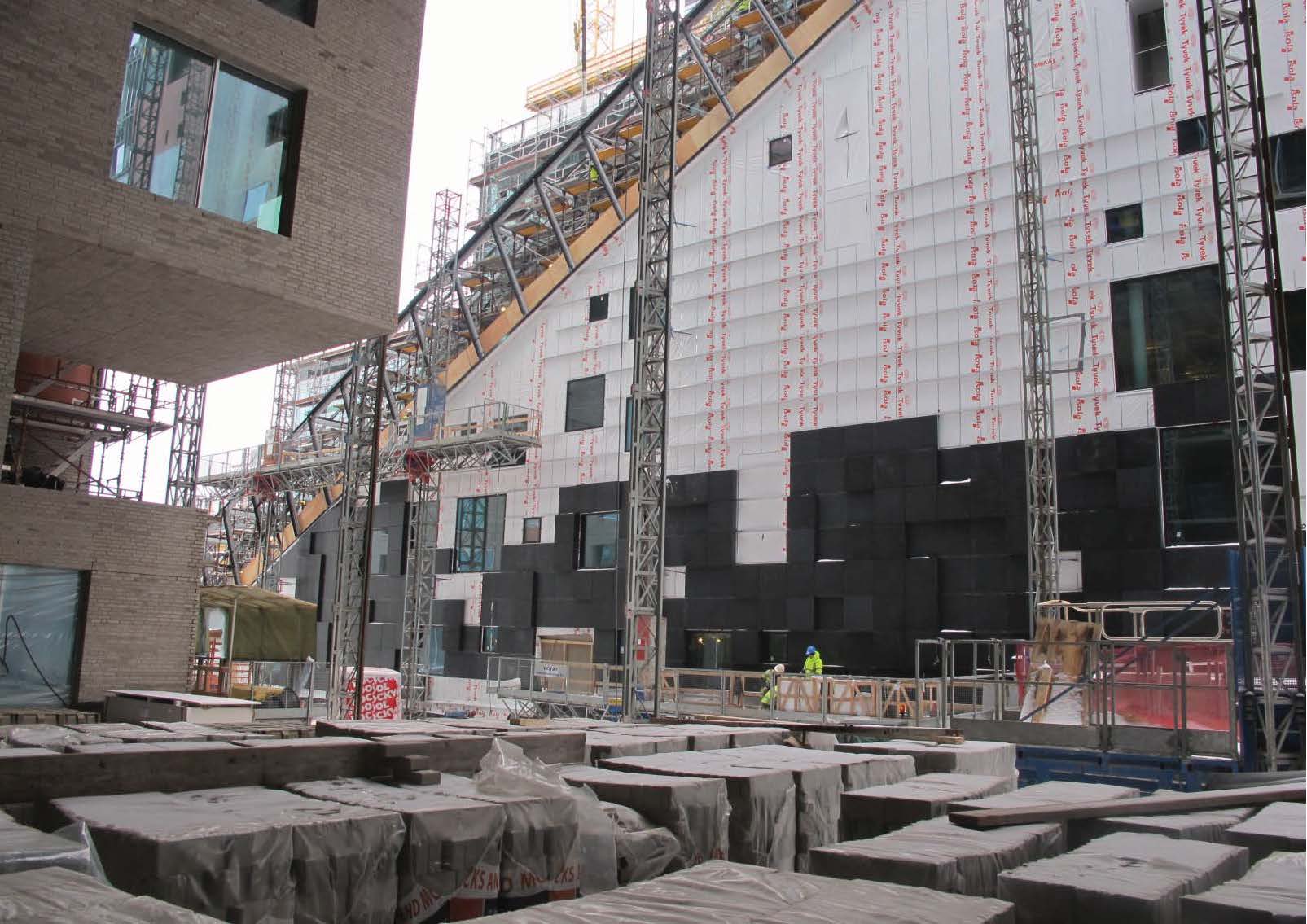
DNB’s new headquarter consist of three buildings with a underground story that connects the buildings together. The building to the far west is designed by Dark Architects, and the concept for the facade was to give it a heavy and solid expression. We did this by playing with different depths and by using a black granite as the facade material.
The sizes of each cassettes is 900mm x 900mm and they are made by gluing 4 mm granite to an aluminium honeycomb system. In total we have more than 6100 cassettes with more than 350 different types. If we are only counting the types there are more than 10 cassettes, we are down to only 25 different cassettes types. With these 25 different types, we cover more than 90% of the facade. To stack all the different cassettes the way we wanted, we tagged all the cassettes on the production drawing. Since they were going to start mounting from the left of the building, we also added which container every cassette should be shipped in. This to make it more efficient on the construction site. Every cassettes is drawn in 3D so we were in total control of the details.
")

")

")
")


