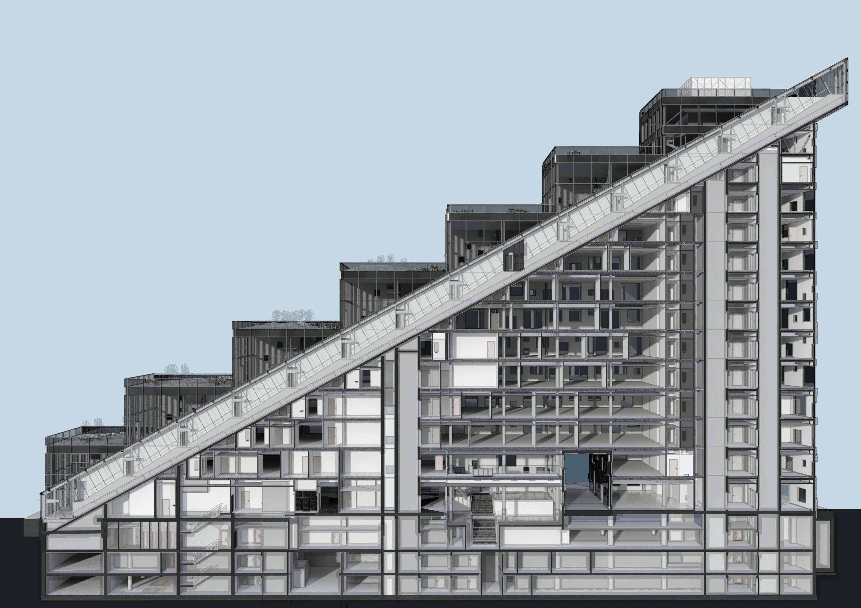
DNB’s new headquarter consist of three buildings with a underground story that connects the buildings together. The building to the far west is designed by Dark Architects, and since the shape of the building i like a stair, it is not a strait forward answer how to make the internal flow efficient with minimum amount of cores. There is also a public roof and a restaurant on the top of the building, so in addition to find the best solution for the many employees in the building, we also had to work out how we could bring the many guests to the spectacular view from the public roof.
The solution was an inclined public elevator that is more than 110 meters long that only stops at ground floor and the top floor, and along the elevator shaft there is a strait stair that connects all the floors in the building. This stair has many names such as «Stairways to heaven» and recently there has been a competition who can be the fastest up all the 303 treads (http://www.dn.no/dnaktiv/2014/05/09/Lping/303-trappetrinn-p-54-sekunder).
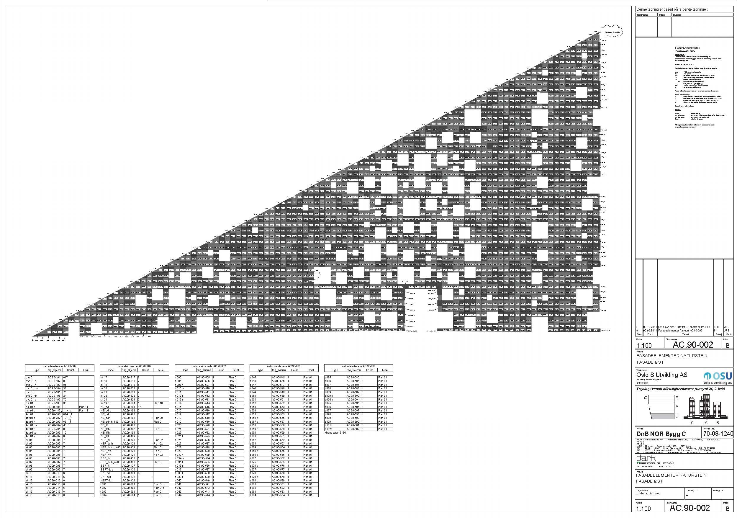
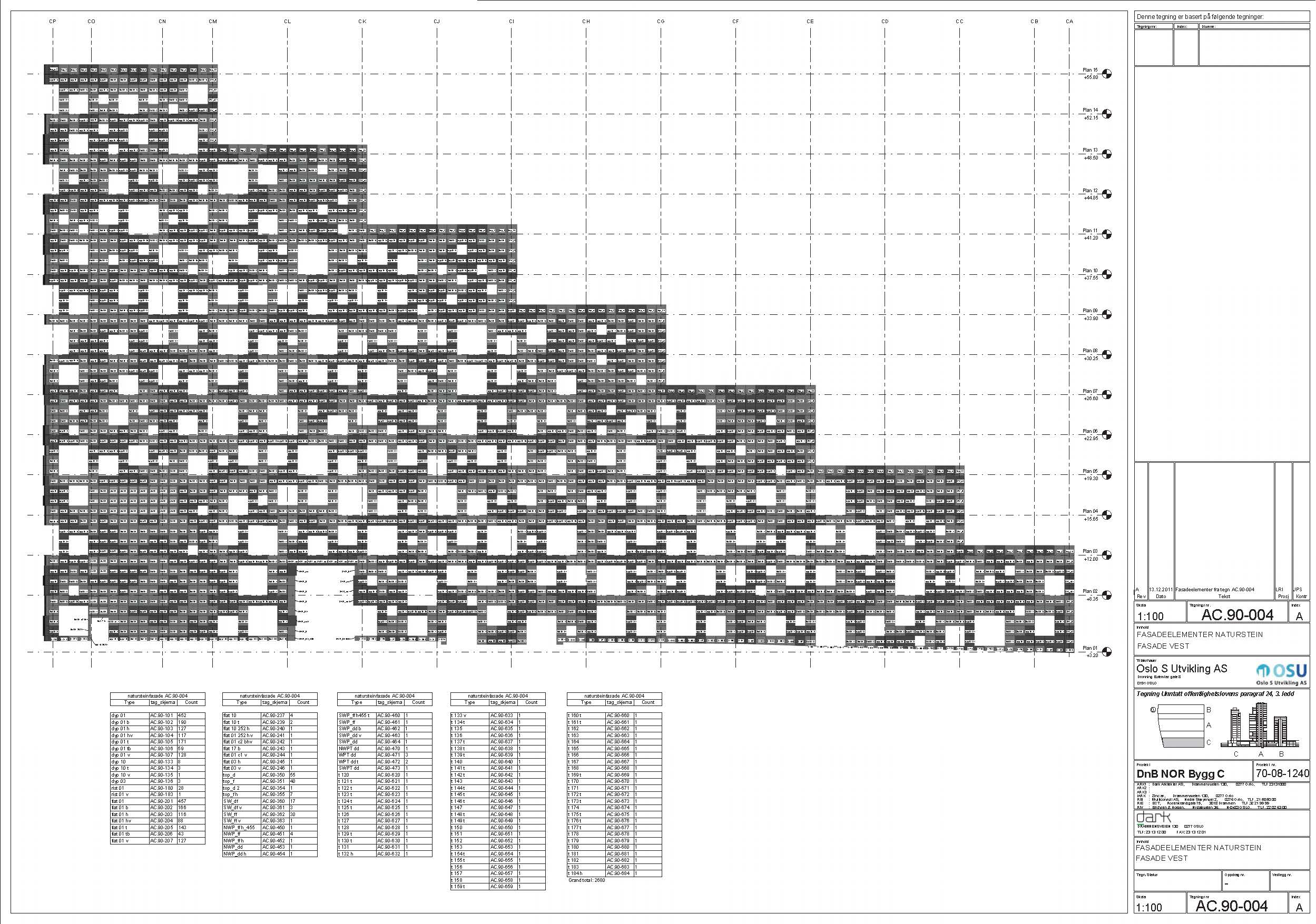
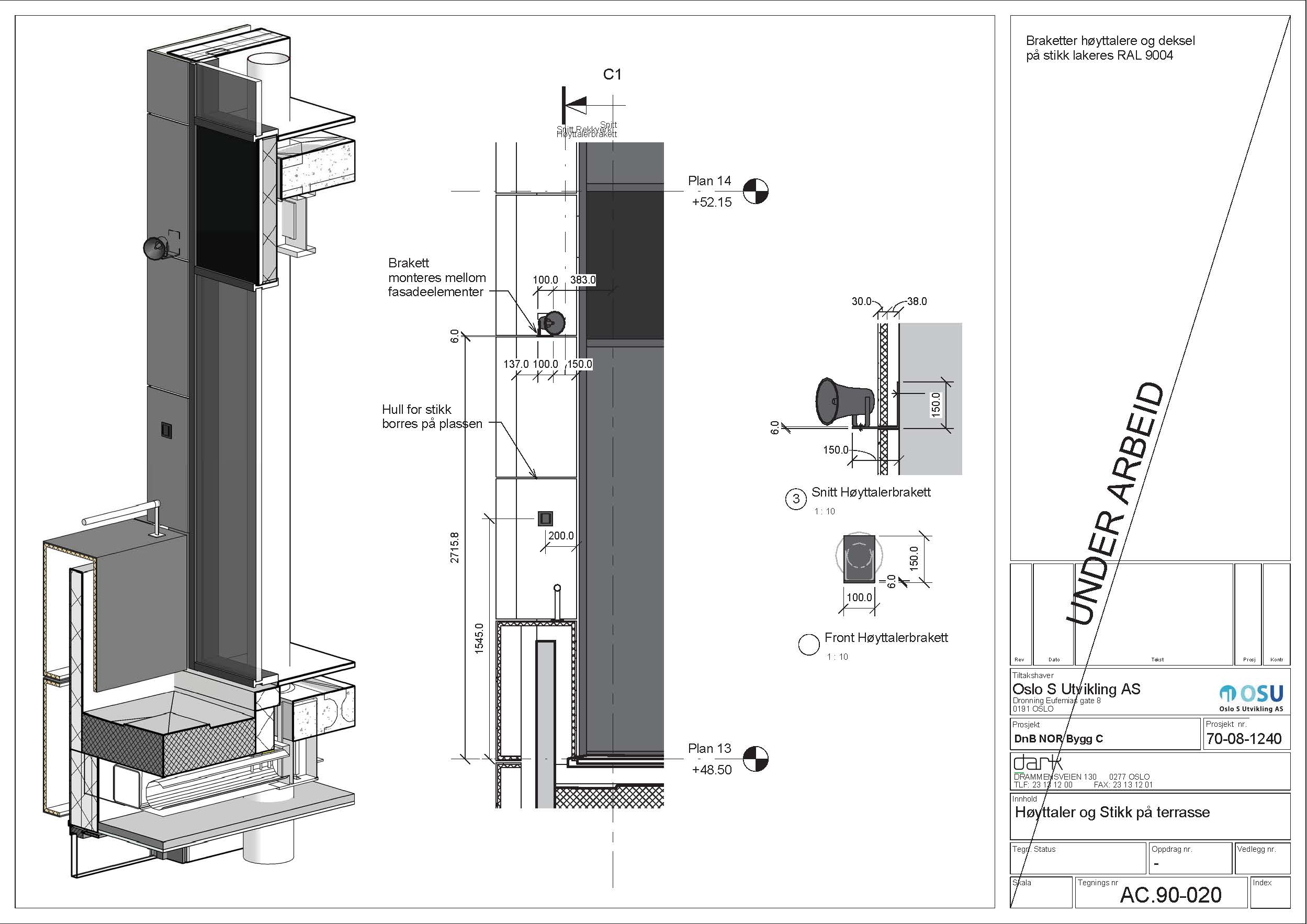
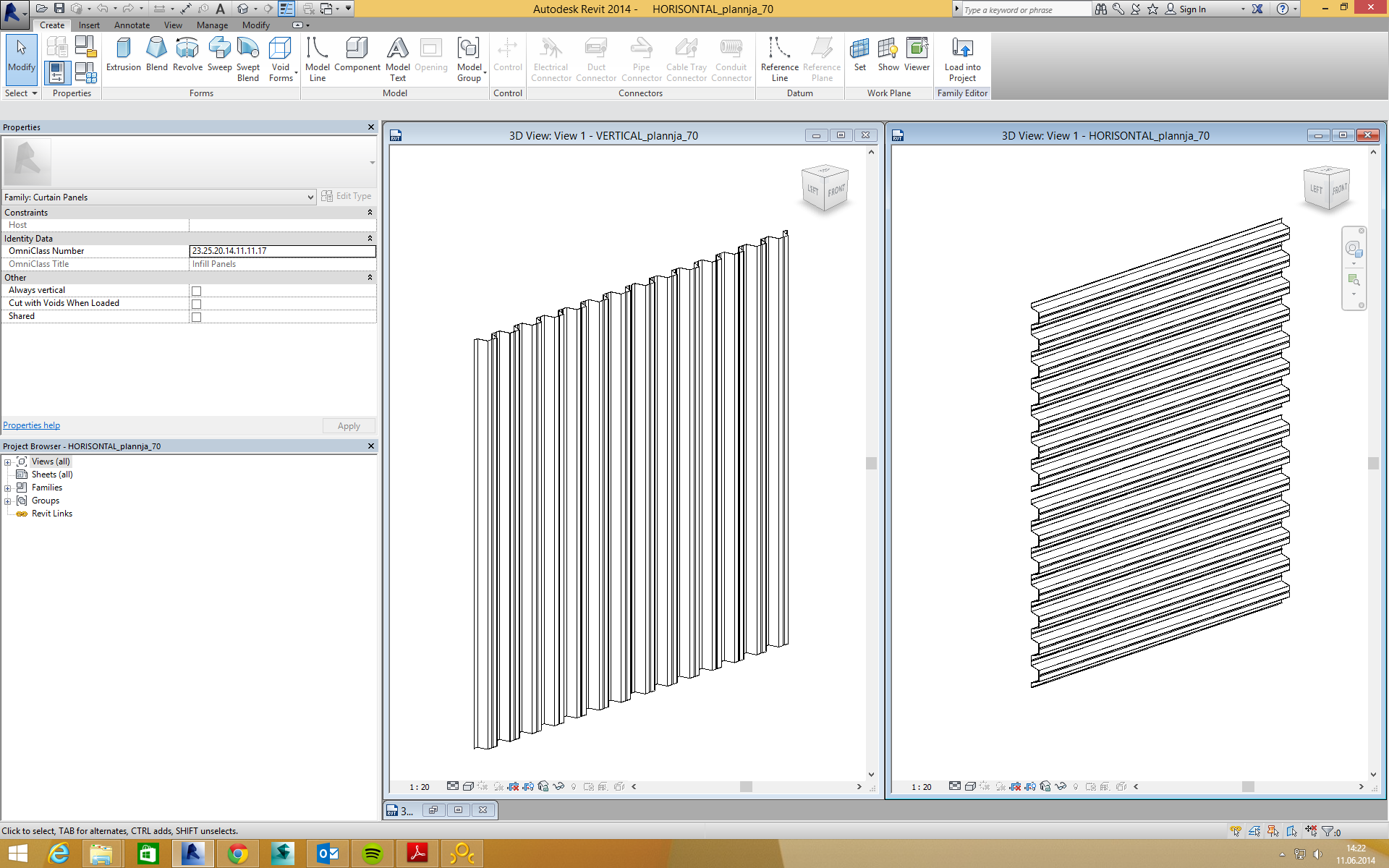
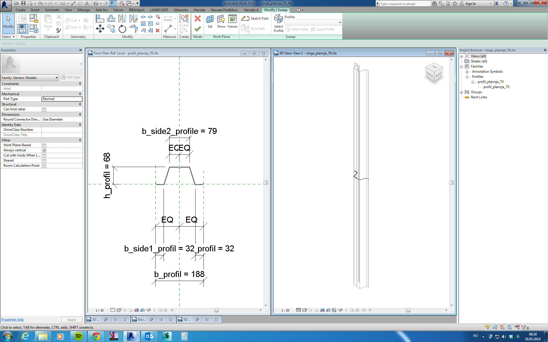
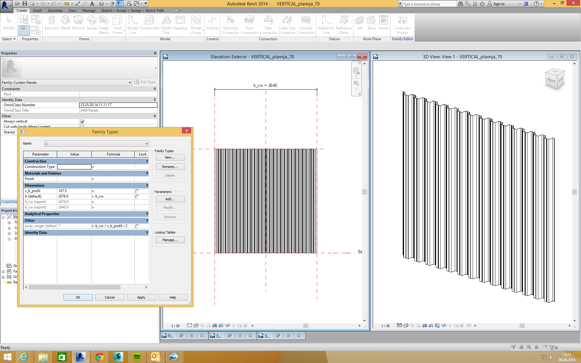
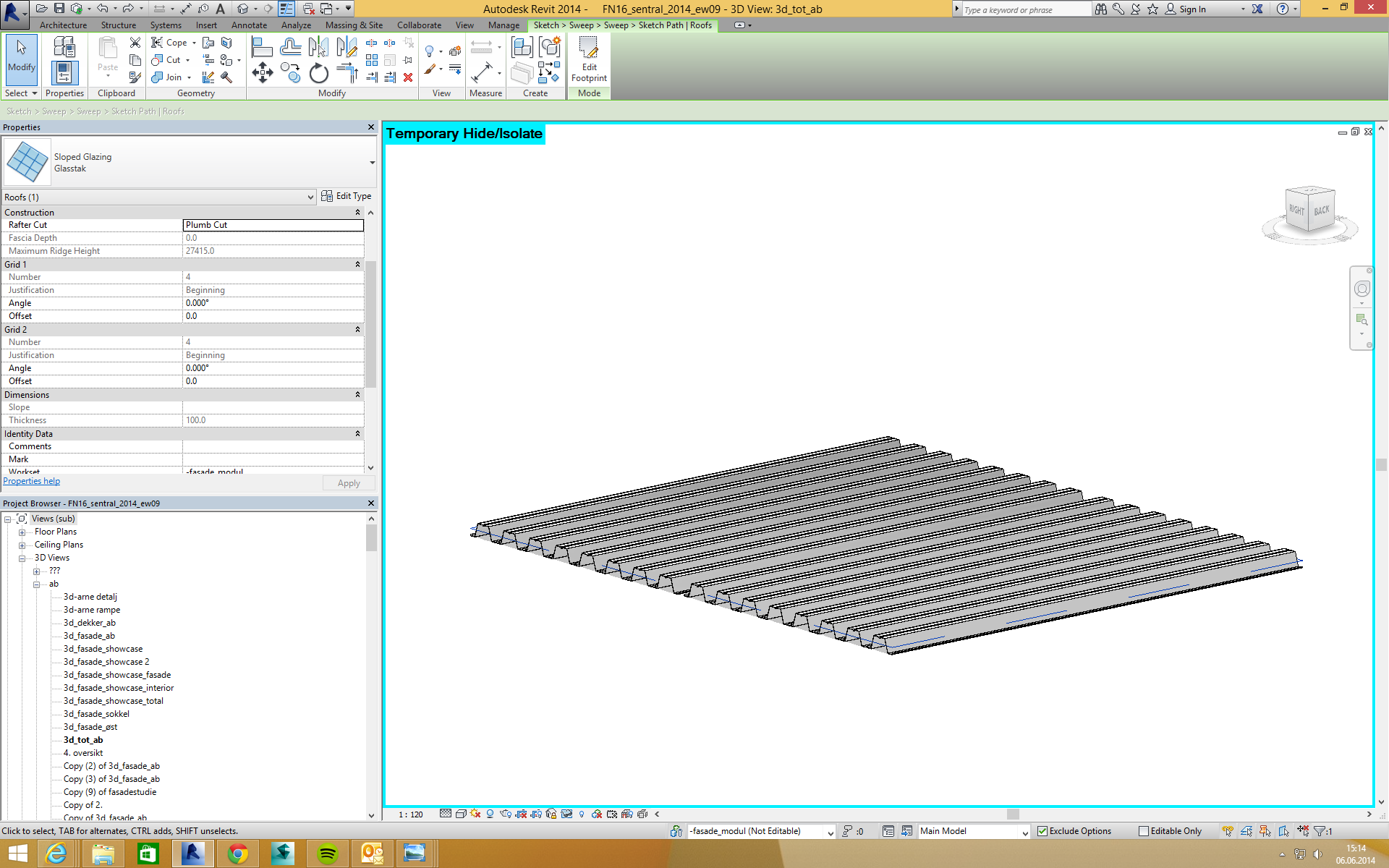
The design process was a joyful ride. When a horizontal slab meets an inclined slab, there will always be some interesting discussion. In addition will the angel of the inclined elevator have direct impact on how the stair will be, since everything is dependent on each other. To feed the project with valuable drawings, I had great success to combine regular floor plans / sections together with isometrics 3D views.


In this project we started using ebeam, and we found it very useful in many meetings and discussions. Suddenly everybody could draw something that everybody could see and participate in.

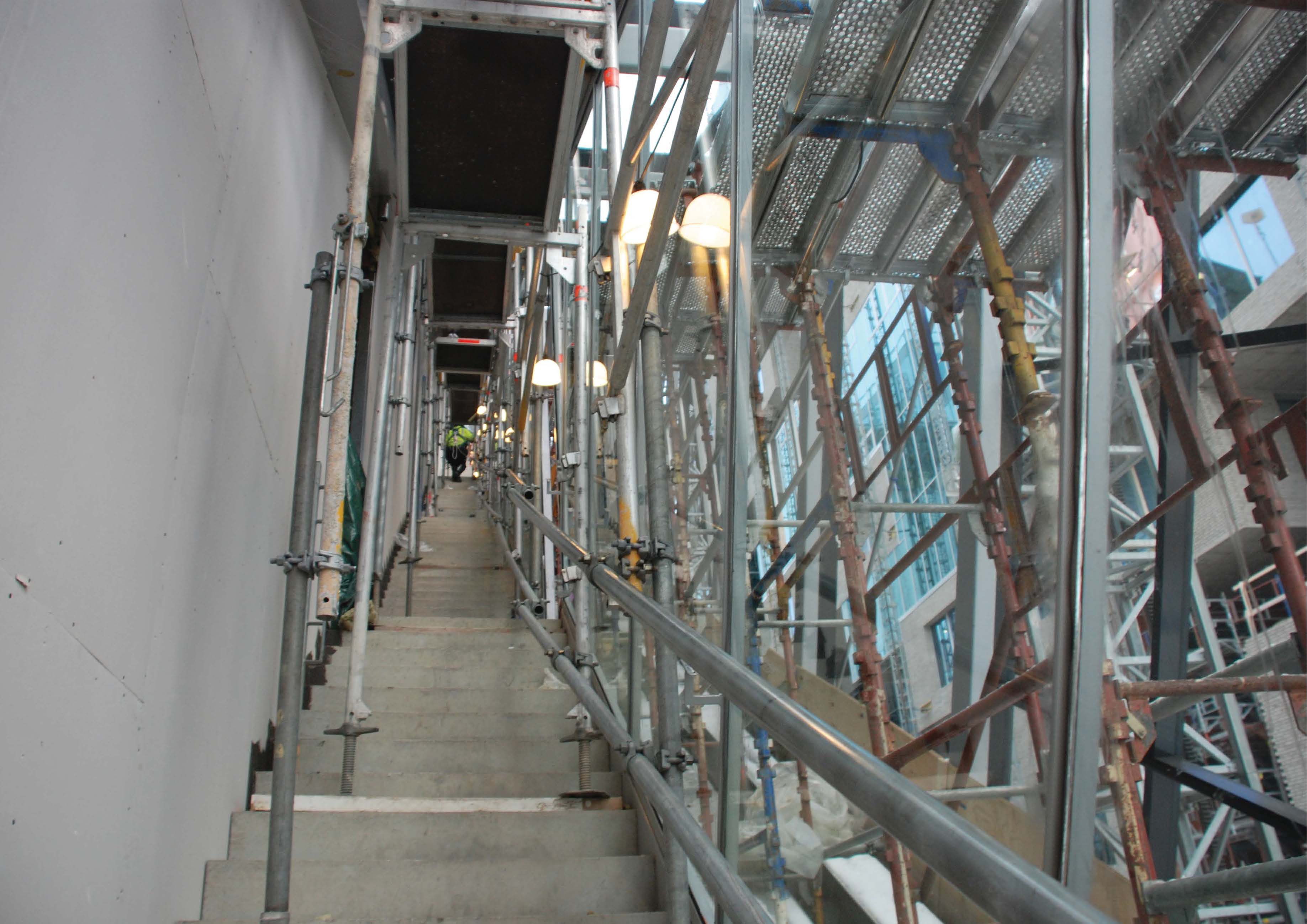
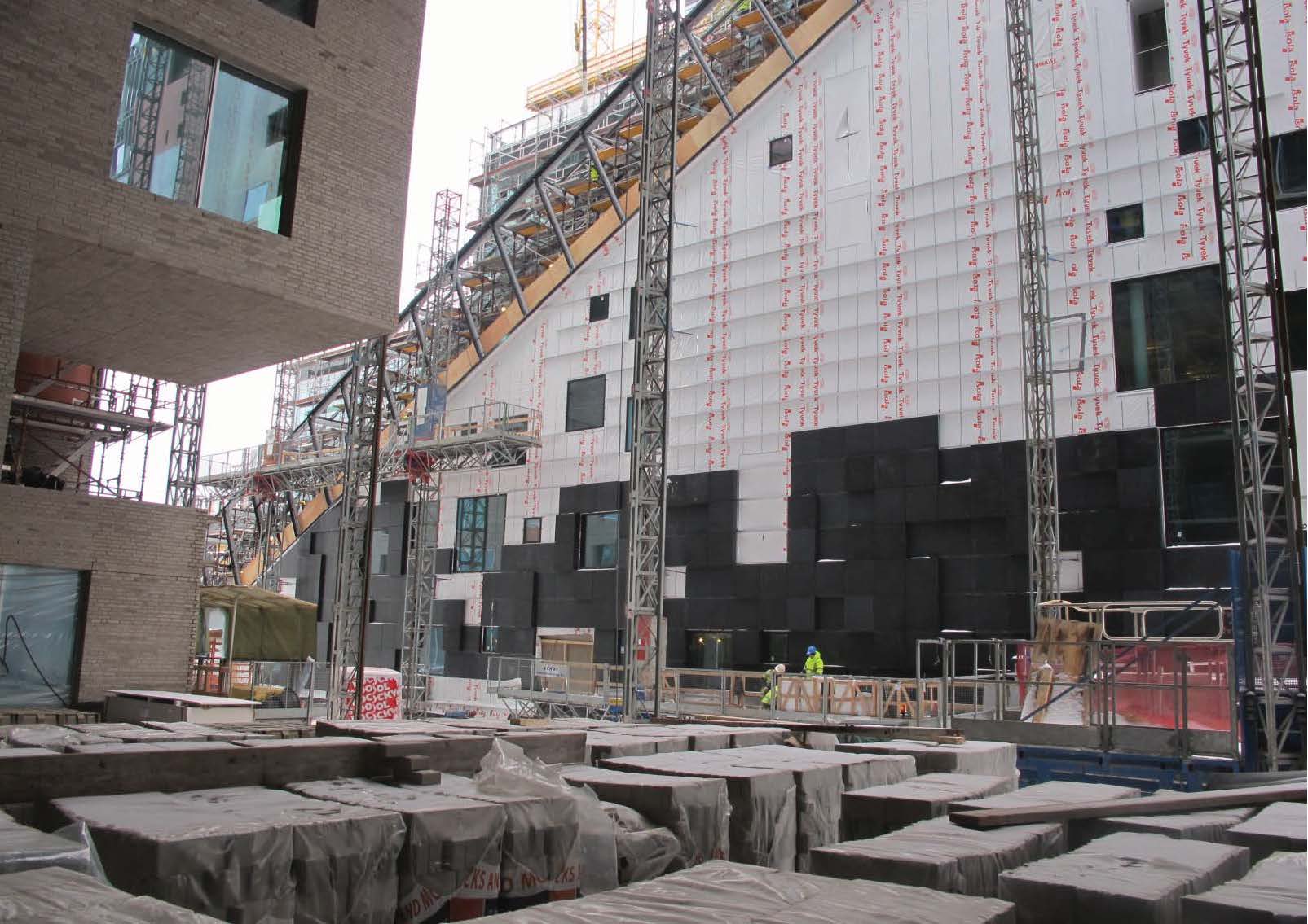
A photo from the construction phase:
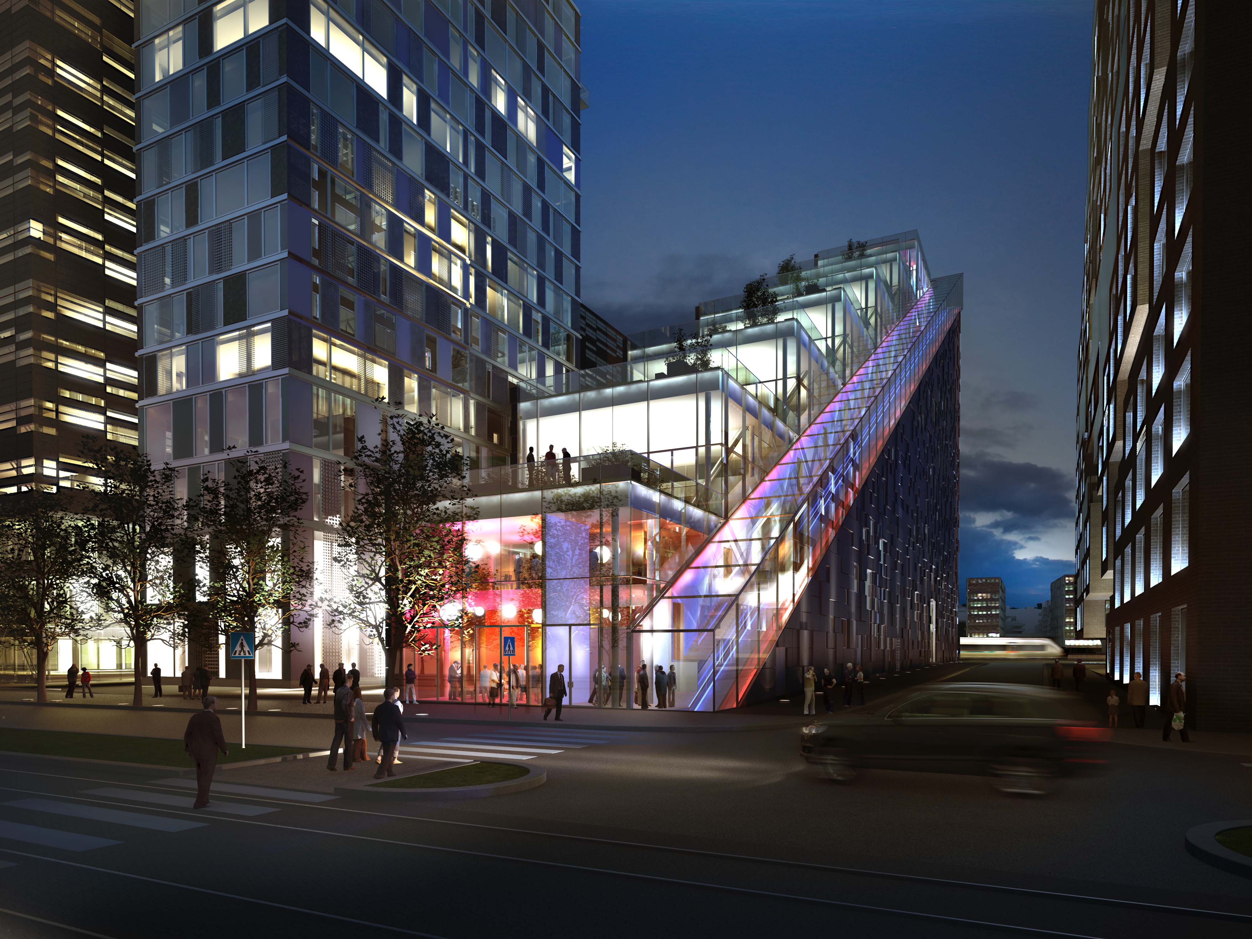
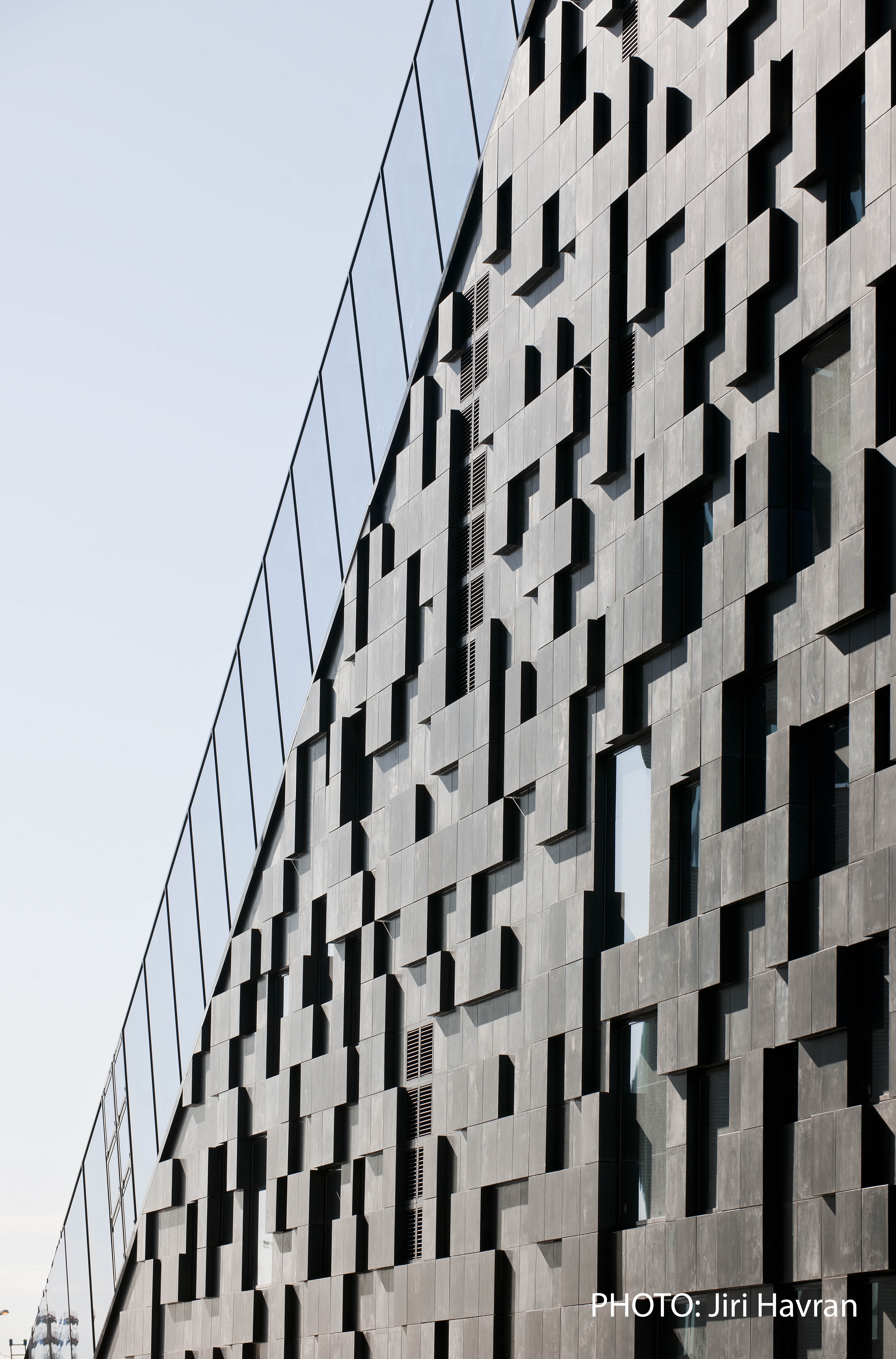
And this is the final results:

Please read more about the project:
http://darkarkitekter.no/en/#/projects/dnb-bygg-c


