Okay, let us talk about the exterior cladding.


It is made of aluminum plates with two different sets of profiles (see picture above). These two different profiled plates are mounted one after the other, and since the module is 2400 mm and the width of every plate is 600 mm, there will be two plates of each type on every module.
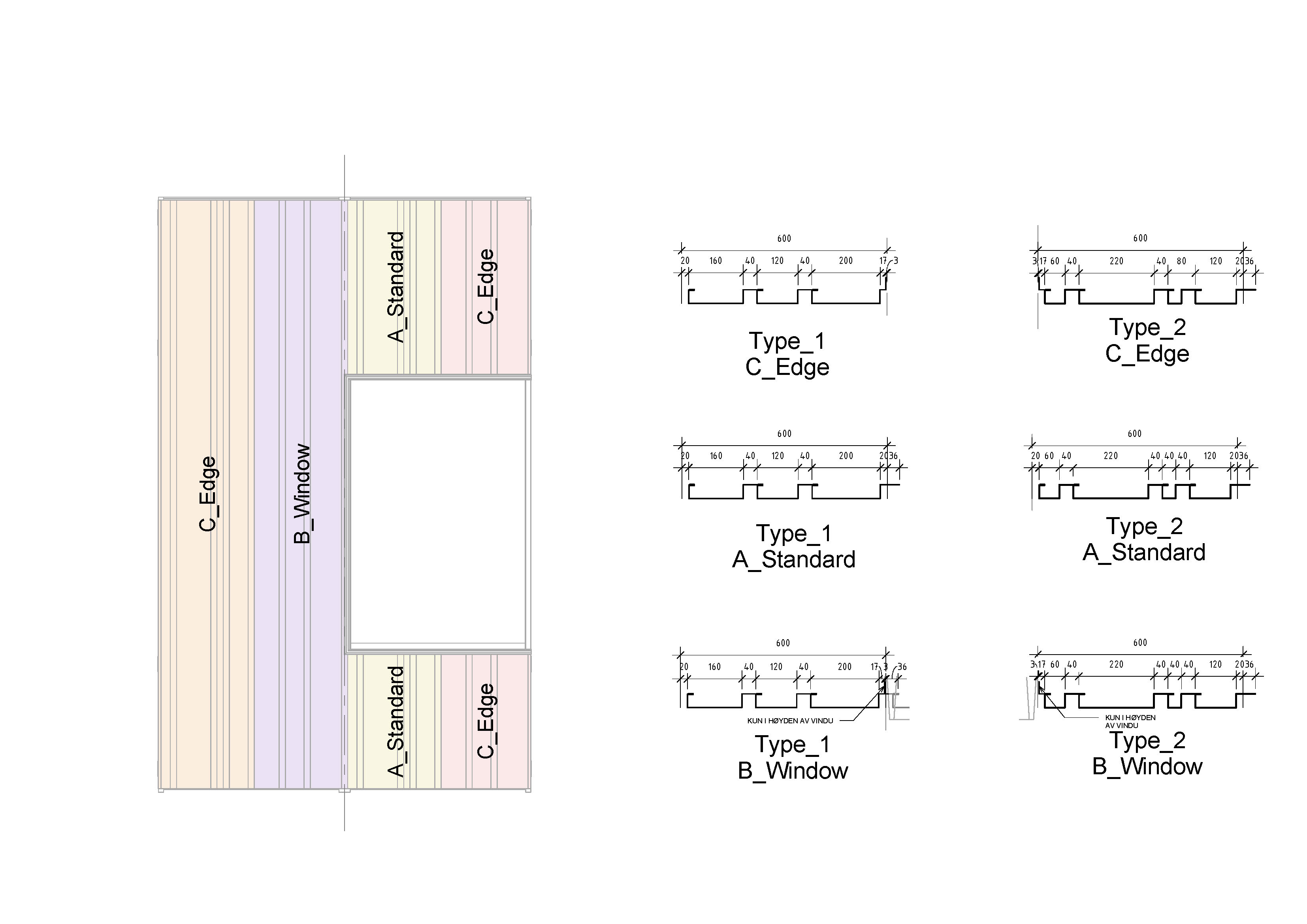

Within every module, the aluminum plates are either on the border of the module, towards a window or towards another plate. These three different positions have an impact on how the edges of the two different plates will be (see picture above).
I have made these two profiled plates as two different curtain wall panel families in Revit for various reason. One of the reason is that sometimes the width is less than 600 mm, and then I want to keep either the left or the right side of the curtain wall panel in a fixed position.This will avoid the position of the profiled plates from shifting from each other (this is illustrated in the video).

The two curtain wall panels is basically made in the same way that I demonstrated in «Family training#1 -CWpanel with array» but in a slightly more complex way. The reason that I can’t do it in the same way, is that I need this family to be 100 % accurate due to production. I can’t simply divide the width of the curtain wall panel with the width of the profiles since this will be to inaccurate. Therefore I have added a little new flavor into the family, and that is a couple of «IF» statements and a profile that can varies between the profile closest to the curtain wall grid (see picture above).

In this way I can simply make a schedule that counts every family and types, combined with height and width parameter, and voilà. You are close to production.

Hi there from Spain.Thank you for share this. I didnt find anything so interesting about cladding in the web. I tried to do your first array example and i got it. But this one is almost imposible just with few pictures, it´s crazy when i cant speak norwegian and the formula is not complete. I would thank you a lot some more information if it´s possible. I leave my mail if it´s necesary.
Sure! Please download the curtain wall panel from this link:
https://drive.google.com/folderview?id=0B_hepuei0ZgkfnFyd0VmNFg3UGVCU2d1SEZtN2dfTHF5SC1iWFZyVXhkdy1MRmowYktsT2s&usp=sharing
Let me know if you have any more questions.
Regards.
Arne
Thank you Arne. I´ll try to make it in the next days, it will be very useful to solve my doubts.
How do you deal with corners?
Good question about the corners. If you are thinking about the external cladding I have only adjusted the width of the panel to trim with the adjacent panel (take a look 2:50 into the video above to see the concept). It is not a perfect way, but it was sufficient in this project.
Regarding how to make a corner module, it is not straight forward. Curtain Walls have so many limitations specially when you try to join CWpanels and CWmullions in a corner (both horizontally and vertically). I will write a new blogpost on this subject late.
arnebjelland, What this effort done for / during construction documents? I am sure you are familiar with LOD standards. This is very close to an LOD400 assembly which is way beyond the scope of typical construction drawings in terms of model complexity. The reason I ask, is that it seem that it would be a little time consuming dealing with client changes (think window locations). I am working on metal pre-engineered frame building and I have the option to follow you footsteps. however my openings are not within a specific module – although the MTL panels are in 36″ lengths from the manufacturer.
I have devised for now use use a reveal to carve out the panel profile. What are your thoughts.
I wish I could share some images with you.
Hi again.
Sometimes you really need to have control with every construction detail to get a good architectural results. I did not trust the manufacturer to be able to deliver good solution for important detail/concepts and therefor wanted to be proactive.
To be honest, I did not think I used more time with this facade compared to «traditional» ways of making drawings, and by using groups it made it very easy to customize the facade «on the way». One of the most important thing you have to consider when you are modeling is when you should start to increase the amount of groups/families. When you start doing this you have to be aware that it will take more time to make big changes.
Regarding the end result of my model, it was close to complete construction drawings for the manufacturer. Due to the lack of interest/knowledge from the manufacturer, my modelinformation was not used by the manufacturer.
Please send me images from your project to my email. I would like to see what you are making.
Greetings.
Tilbaketråkk: Case study #3 Part C: The final result | Digital story of an architect